

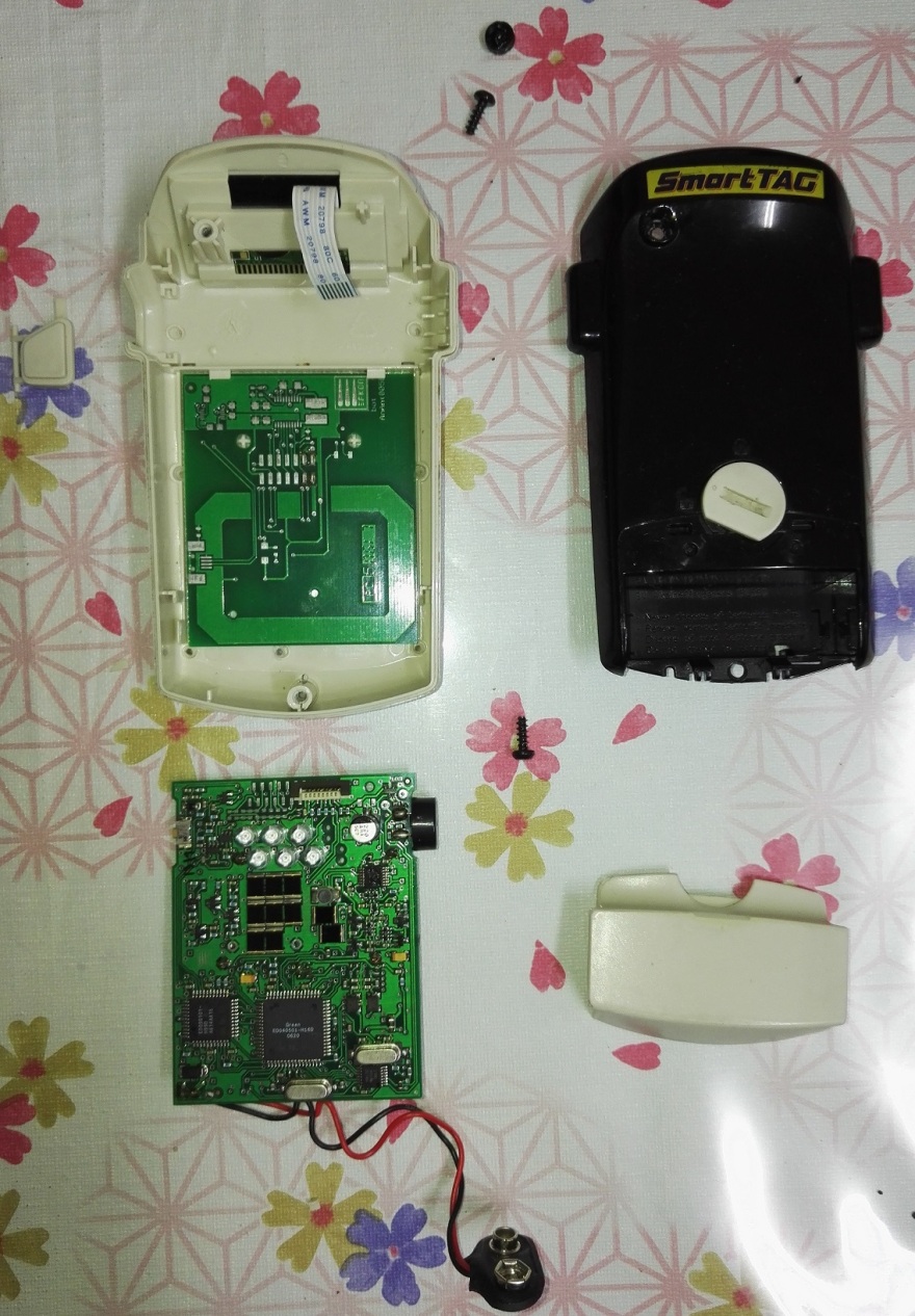
The old generation SmartTag is made up of 2 PCBAs, enclosed in the black and white plastic casing, secured with 2 screws.
One screw is at the 9V battery compartment and it is visible.
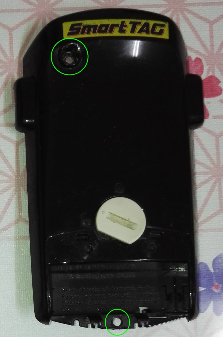
The other screw is at the other end hidden right beneath a black hollow plastic cylinder as shown. It is difficult to remove that thin piece of black plastic cylinder. It is believed that the manufacturer design it this way to prevent user from tampering the product. You might want to try to remove it with a needle. Alternatively, if your old generation SmartTag‘s warranty already expired, just use a screwdriver to pierce through the top portion of the black hollow plastic cylinder to reach the screw beneath.
Unscrew both screws and carefully open up the casing. The casing has some snap-in-hook design in some part of the plastic. Open up the casing carefully.
What's Inside?
There are 2 PCBs within the plastic casing, the main PCBA and the TouchnGo (TnG) card-detection-PCB.
The main PCBA is the one with 6 Infrared LEDs, a couple of ICs, a buzzer and is connected to the 9V battery connector. The LCD is connected to the main PCBA via ribbon cable too.
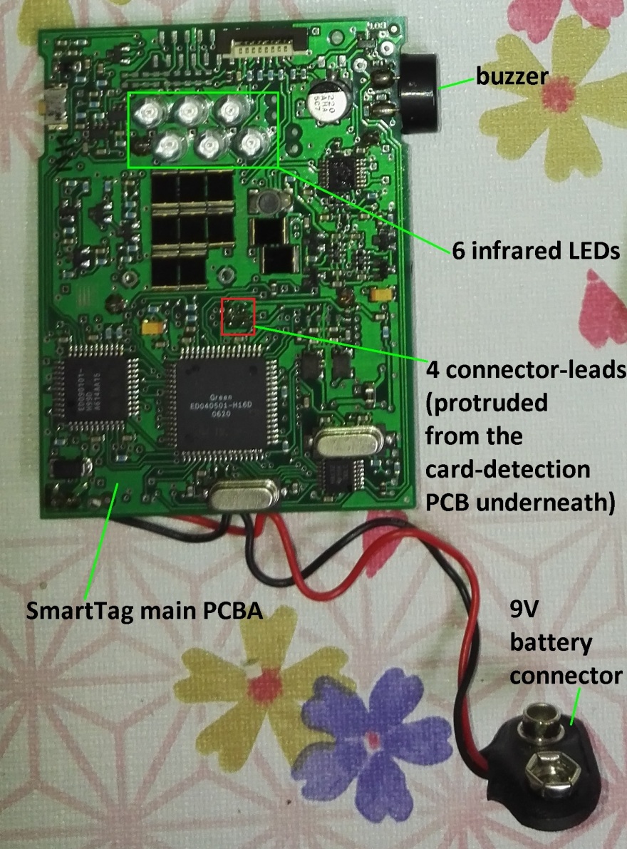
Refer to the position of the 6 infrared LEDs. It is located close to the LCD display and they are facing the black color plastic casing. That’s the communication gateway between SmartTag and the SmartTag sensor at the toll plaza. If you ever try passing through the toll plaza with the black plastic casing facing downwards, or, black plastic casing facing upwards but covered with palm, the SmartTag sensor will encounter difficulty in detecting the SmartTag and you will be denied from passing through the SmartTag lane.
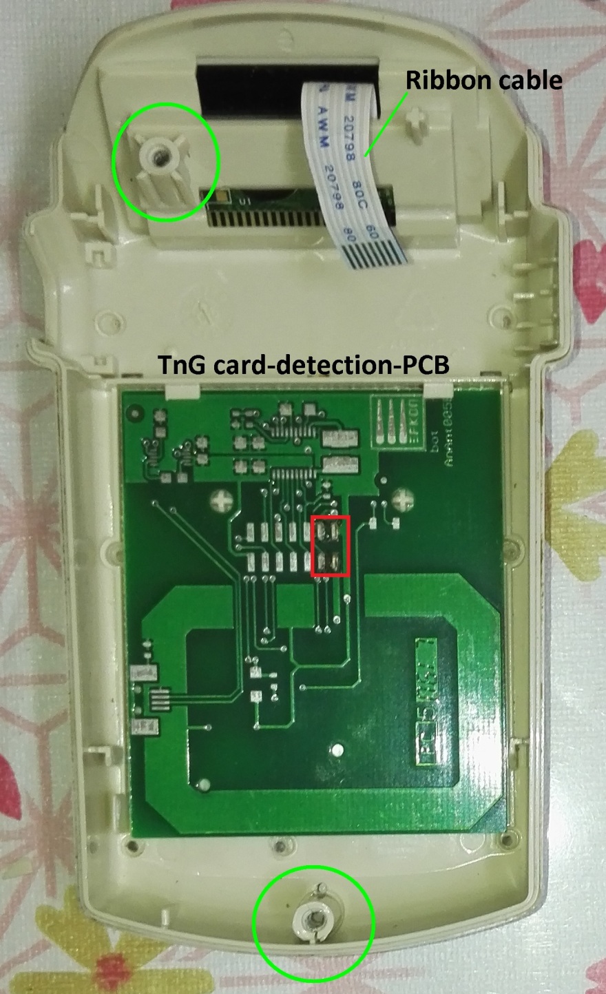
The second PCB is almost a blank PCB with minimum component on it. This is the TnG card-detection-PCB. There are thick rectangular lines on the PCB which is believed to be antenna-like or RFID-like design, meant to detect the existence of the card and to read the card content.
Both PCB are connected by 4 connector-leads. (Refer to the 4 solder pads as shown in the red rectangular in the picture above.)

The design is actually not robust because the entire two printed circuit boards are connected together only by that 4 connector-leads!!! The SmartTag designer seems intended to support both PCBA with the plastic casing, but unfortunately, the plastic casing doesn’t really do the job well due to a lot of spacing tolerance. It doesn’t secure the boards firmly in place.
That is why if the SmartTag encounter multiple drop shock or if you frequently dump the SmartTag back into your glove box after passing through the SmartTag lane, the shock encountered each time will eventually break the solder point of that 4 connector-leads one fine day. With that solder break, the SmartTag main PCBA will not be able to detect nor read the TnG card because it can’t communicate with the card-detection-PCB through those 4 connector-leads any more. Customer will have to send the SmartTag for repair or purchase a new SmartTag. That is where business comes in.
Let's Fix It
So, if you encounter such problem, where the SmartTag can’t read your TnG card, either occasionally or consistently, no worry. You can either send the SmartTag back to authorized SmartTag repair center for repair, or, if it is too costly for you to send the SmartTag back to authorized SmartTag repair center, DiY it.
Carefully unscrew the casing and inspect if there is any solder crack at the 4 connector-leads. If there is no solder crack, sorry, this article can't help you. If there are solder crack indeed, and if your solder skill is ok, do it yourself to repair the solder crack. Else, get help from any nearby electronic repair shops that perform soldering. It is a simple soldering job; even normal hand phone repair shop should know how to solder it. But, nobody will have any tools to test the result after soldering. The only way to test the repair result is by passing through a SmartTag lane.
To repair the solder crack yourself, firstly, take some pictures of the 2 PCBAs (while they are still partially connected) to record down the orientation of the PCBA. You don’t want to wrongly solder both PCBA together and cause your SmartTag to be malfunctioned.
Then, completely de-solder the 4 connector-leads from the main PCBA. Be careful on the soldering tip’s heat to prevent the gold platted pad on the PCB from wear off during the de-soldering process.
Clean up the PCB via-holes for those 4 connector-leads at the main PCBA. You will need to solder back the 4 connector-leads through these via-holes later.
Now, you have detached the 4 connector-leads from the main PCBA. Proceed to solder the 4 connector-leads base pins firmly on the TnG card-detection-PCB.
Plug the 4 connector-leads through the main PCB via-hole again. Ensure both PCBs orientation are correct, same as the pictures you took earlier.
Then, solder the 4 connector-leads on the main PCBA. Job done.
Assemble back both PCBAs into the plastic casing accordingly. Ensure the PCBA guide hole are in the plastic parts guide pins.
Remember to connect back the LCD ribbon cable.

Assemble back the plastic casings and tighten the screws. Connect back the 9V battery. Press the side button to check if the LCD is functioning and able to read your card.
For more DiY ideas, visit mydiypapa.com or contact us.
Subscribe to our blog via email or join our Facebook page.
Pingback: Toy fan repair -